ON-LINE OIL DILUTION MEASUREMENT

Click here for downloadable brochures

Printable Version


Introduction

On-line measurement of oil dilution is of interest in light of new environmental regulations imposed on today's high-performance engines. In particular, after-treatment devices such as diesel particle filters (DPF) need to be periodically re-generated in order to eliminate their soot content. Such re-generation process is typically performed by using post-injection cycles that can induce a transfer of fuel to the lubricant, resulting in oil dilution.

A new methodology was recently developed by DSI sprl and TOTAL France for monitoring oil dilution on running engines. It is based on lubricant labelling using a new radiotracer compound, which is representative of the oil content into the sump.

Measurement Principle

The new, patented method is based on lubricant labeling using a new radiotracer compound, which is added to the lubricant. A few ml of labeled compound is mixed to the lubricant as soon as the engine is started. During engine operation a small volume of oil is sampled from the engine sump and it is circulated continuously into a measuring chamber where specific activity of the oil is monitored. The dilution measurement consists in monitoring the signal (gamma-rays) emitted by the radiotracer and in converting any variation in terms of oil dilution.

Data Acquisition

The measuring device takes into account temperature effects. Moreover, oil is pressurized in the measuring chamber in order not to be affected by aeration.

A new radiotracer has been developed, with a short half-life of <40 hours. In cases where oil consumption is significant during the test, the tracer can be combined to specific organic compounds to obtain a distillation interval similar to the base oil contained in the engine.

A few ml of tracer is added to the lubricant. The engine is run a few min. to homogenize in the oil. The homogenization process is monitored by circulating the oil in the measuring chamber and dilution measurement can be started as soon as the signal stabilizes.


D-LUBE

The dilution monitoring device "D-LUBE" includes a measuring chamber where the engine oil is circulated. Oil flow and pressure in the chamber are selectable. A radiation detector is installed against the chamber. It offers a high efficiency for detecting gamma-rays emitted by the radio tracer compound. Both chamber and detector are enclosed in a thick lead structure to shield against external radiation coming from natural background, and coming out from the engine that also contains labeled oil. The measuring device is designed in order to be easily installed in the vicinity of a test bench. Setting up and connection of the device are done within minutes.

D-Lube
The chamber is connected to the engine using ½" hoses. A speed-regulated pump is installed downstream of the chamber to circulate lubricant, and an adjustable valve is located at the outlet of the chamber in order to regulate the pressure inside the chamber.


Automatic T° Compensation

During engine operation, temperature changes induce density variations. Without compensation, any temperature increase would increase the dilution signal since for the same lubricant activity the total volume is higher, and vice-versa. It is thus important to take into account those density variations. 
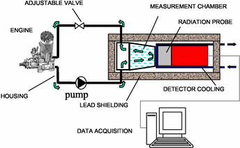
A temperature measurement is performed in the measuring chamber in order to correct the dilution measurement, using the following formula:

Dcorr = D(T)-c(T-T0%)


Where :
Dcorr is temperature corrected dilution
D(T) is dilution at a measured temperature
c is the temperature calibration coefficient
T0% is a reference temperature for 0% dilution

Gas

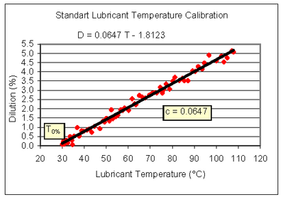
A calibration measurement has to be performed in order to determine coefficient c. The calibration consists of circulating labelled but non-diluted lubricant in the measuring chamber, and measuring specific activity variations associated to temperature changes. Activity variations are expressed in terms of oil dilution and calibration typically yields a first-order curve where the slope is the above-mentioned coefficient c. The reference temperature T0% is the starting point of the curve. Such calibration has to be performed once per type of lubricant.


Example: Diesel Engine Monitoring

A 2.2 litre/4cyl. diesel engine is run at high post-injection rate, at low RPM and low torque of ~35 pound-feet. A 100 ml sample of lubricant is taken periodically for Gas Chromotography (GC) measurement. GC measurement results (green spots) are superimposed to the on-line results (red curve), showing an excellent correlation between the two methods. The thin dark lines are second order fits from experimental data obtained with both methodologies: one can see that they are nearly superposed.


Temperature Calibration

© ANS Technologies Inc. 2010. All Rights Reserved.